These
are intentionally very tight. Using a little grease greatly reduces
the difficulty of fitting these.
In the front and rear of each tread assemble the locking mechanism
(Fig 10).
With the Recanto be careful screwing in the threaded bush as it is
possible to split the tread if this is forced too far in.
The first and last baluster of each tread will pass through 2 treads.
NOTE:
Care should be taken at this stage not to set the grub screw too far
in to avoid scratching the baluster as it is passed through the tread.
Fit
the first and last balusters of each tread, lining up the treads as
you go, Always work from the landing platform down. Do not forget
to add the baluster trim rings as you fit each baluster. The opening
baluster secures into a steel cup which is fixed to the floor (Fig
11).
Next assemble the bush into the underside of the remaining balusters.
Screw these to the treads without tightening too firmly as these will
be adjusted later on. Note at this point that the holes in the tread
for these balusters are formed in the shape of a slot to allow some
adjustment.
For
individual rises (outside 190 - 210mm) it will be necessary to cut
the balusters to length. This can be done by adjusting the baluster
to the centre of the slot then taking A line between the first and
last
baluster on the tread. Any slight inaccuracies can be taken out using
the slot.
Insert the strengthening
pipe inside the handrail. Starting at the top begin to assemble
the handrail to the balusters (Fig.12). Leave
enough spare at the bottom to be able to cut exactly to length afterward.
Check each baluster carefully with a spirit level to ensure it is
vertical in all directions before driving in the screws.
Place the end caps supplied on the ends of the rail to finish it
off.
Brio
For the Brio Carefully position the anti-slip tread mats.
Both systems
As both Brio and Recanto kits are designed to he installed either
clockwise or anti-clockwise it is necessary to drill the landing
platform on the correct side to accept the landing balustrading
supplied. In each kit you will find the relevant template to help
with this.
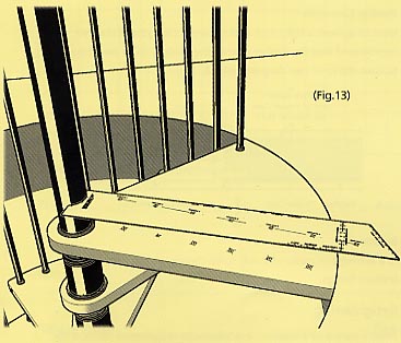
Place the template on the landing platform and drill the holes following the guide. Assemble the platform balustrading (Fig.13).

Adding
strength to your balustrading
A number of optional items are available to increase the rigidity
of the balustrading These should be used wherever possible to ensure
a safe
installation.

Baluster
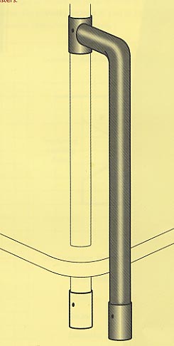
to Floor Connector
Can be used on the first baluster of the staircase or on landing balusters.
Baluster
to Wall Connector
Use this to tie a baluster into the apron lining of the well opening
or to finish landing balustrading against a wall.
Greatly increases the rigidity of the batustrading.
Baluster
to Baluster Connector
Can be used where raking balusters pass landing balusters to add strength
to both.
Landing
Balustrading
A number of landing balustrading products are available for you to
continue the balustrading around your well opening.
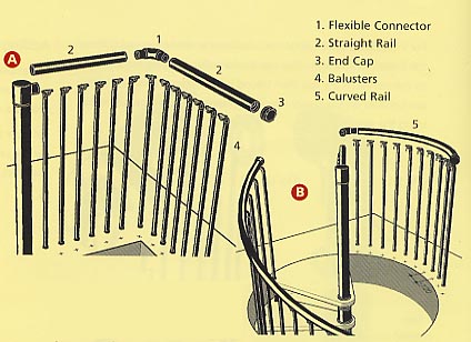
Both flexible and straight handrails plus flexible connectors, and
wall connectors are offered. Two examples are provided here which
demonstrate how these components can be used to safely and attractively
guard the stairwell.
Example A
A flexible connector is used to turn the landing platform balustrading
into an L-shaped run of balustrading. At the corner a further flexible
connector is used and finally an end cap and a wall connector are
used to make a firm connection to the wall.
Example B
Is similar to 'A' but shows the use of a curved rail. Again a flexible
connector is used to turn the landing platform
balustrading into the curved run with an end cap and a wall connector
used to complete the installation.
Landing Balustrading Components
End Cap
Used to finish a run of handrail. Where possible should also be
screwed to the wall to provide a stronger run of balustrading. Each
stair has 2 included to start and finish the handrail.
Curved Rail
Available in 6m lengths this rail is capable of being bent to achieve
the required curvature and is used primarily around circular well
openings.
Straight Rail
Identical in appearance to the curved rail this is available in
3m lengths. It is supplied with a timber core to increase the rigidity
of the rail and to maintain a perfectly straight run.
Flexible Connector
Used to achieve a tight turn and to connect lengths of rail. We
recommend that the timber core of the landing rail is pared down
to span the joint (see diagram ).

Retightening
After a period of 2 weeks it is advisable to retighten all baluster
to tread fixings plus the main centre pole nut at the top of the flight.
This will ensure that the staircase remains taut.

Gamia Spiral Staricases


